A thermal imaging camera can reveal temperature distributions that are difficult—or even impossible—to detect in an ordinary image. A visible-light camera, meanwhile, can show equipment, structures and the surrounding environment in much finer detail. During a UAV mission, operators often need both types of information at the same time.
For this reason, multi-sensor gimbal cameras provide different ways to display the two channels. A fused view combines thermal and visible-light information in a single image, while a split-screen view displays the two channels independently. Each supports a different stage of the decision-making process, and it is difficult for one mode to cover every task.
In actual operations, the key question is: Which display method helps the operator detect, locate, verify and document a target more clearly while minimizing ambiguity? Using the HEQ K40T quad-sensor gimbal camera as an example, this article explains its four display outputs, the complete infrared super-resolution fusion processing chain, resolution and registration limits, the value of split screen, and a practical field and procurement test workflow.
The K40T’s four main display outputs
A multi-sensor gimbal camera can provide several image outputs. Their names may sound similar, but their data sources and purposes are different.
Visible-light imaging answers, “What is this, and where is it?” Thermal imaging shows thermal differences and temperature-distribution characteristics. Infrared super-resolution fusion connects the two types of information, while split screen allows the operator to see the boundary between the source data clearly again. All four outputs can work together within the same mission.
How infrared super-resolution fusion works
The K40T’s infrared super-resolution fusion connects two processing stages. The first stage applies super-resolution processing to the thermal image. Using AI and interpolation, the system converts the 640 × 512 image captured by the thermal detector into a 1280 × 1024 image. Both the width and height are doubled, producing four times the total number of output pixels. At the same time, the visible-light sensor captures its own image.
The second stage is pixel-level fusion. The system processes the timing, field-of-view differences, resolution differences and physical positional relationship between the two optical channels. It maps the visible-light information used in the fusion process to the corresponding locations in the thermal scene. After registration, a dedicated fusion algorithm generates the final composite image. The operator can adjust the fusion intensity or switch to split-screen display.
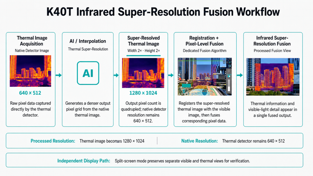
K40T infrared super-resolution fusion processing chain.
Why pixel-level fusion depends on registration
The visible-light lens and thermal lens are installed in different positions, so there is a physical distance between their optical axes. The two sensors also have different fields of view and resolutions. Pixel-level fusion therefore needs to identify where the same scene location appears in each image before the images can be combined.
The system can achieve good alignment at a reference distance, but residual misalignment may still appear when target depth changes. When a nearby pipe and a distant cabinet are visible at the same time, a single two-dimensional mapping cannot perfectly align every depth. Movement of the aircraft, gimbal or target can also create temporary misalignment because of differences in the imaging timing of the two sensors, the rolling shutter of the visible-light camera, the thermal detector’s integration time and processing latency.
When the visible-light camera zooms or the system switches cameras, the relationship between the fields of view changes, and the registration parameters may need to be updated. Features seen by the two spectral channels do not always correspond one to one: a coating boundary visible in the RGB image may have no temperature difference, while an anomalous area in the thermal image may lack a clear surface outline. When evaluating fusion performance, the actual working distance, focal length, scene depth and movement conditions should all be included in the test.
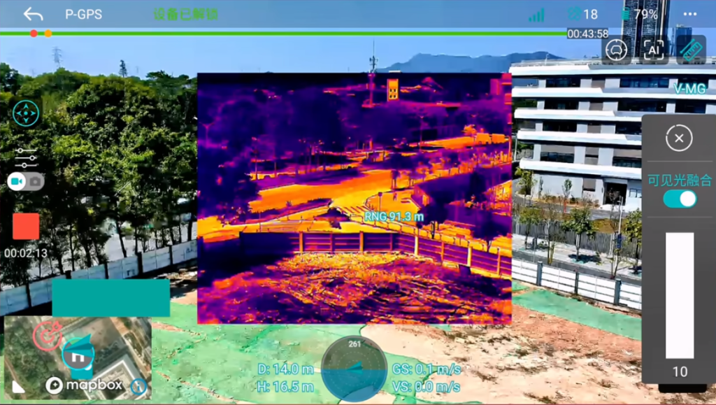
A fused image calibrated at one reference distance may still show residual registration errors when objects are located at different depths.
What a fused view can provide
The purpose of infrared-visible image fusion is to concentrate the complementary information from two sensors into a single image. The thermal channel provides temperature-related contrast, while the visible-light channel contributes edges, textures and familiar scene structures.
For a UAV operator, the most direct benefit of fusion is faster spatial localization. A thermal anomaly on a large facility may be easy to detect but difficult to associate immediately with a particular connector, panel or area. Visible-light details in the fused image can make this relationship more intuitive, especially while the aircraft or gimbal is moving. However, a fused image is better suited as an operator-assistance view. If a mission involves temperature assessment or inspection evidence, the original thermal data should still be viewed and retained.
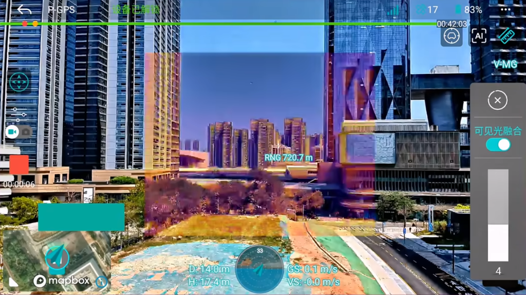
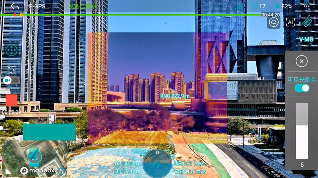
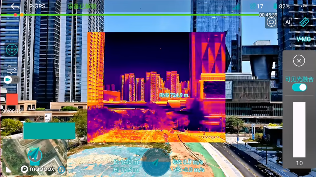
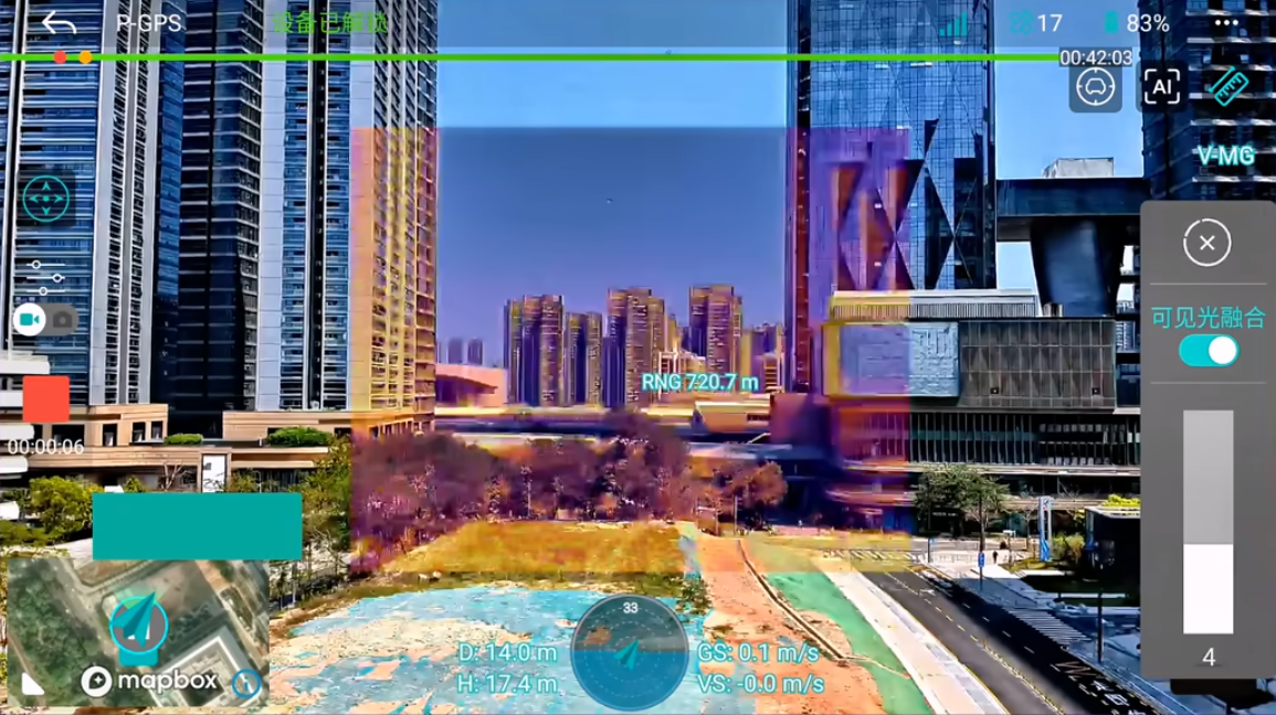
Different infrared super-resolution fusion intensities
Why is split screen still needed?
Fusion combines information from two channels into one processed image, improving observation efficiency while making the boundaries between information sources less distinct. Split screen gives the visible-light and thermal channels their own independent windows, making it suitable for stages where evidence needs to be checked.
Confirm which sensor contributes a detail
An edge in a fused image may come from a genuine thermal boundary, visible-light surface texture, or the effects of super-resolution, registration and fusion processing. After switching to split screen, the operator can compare the two complete source images and confirm which channel actually contains the critical feature.
View the complete thermal palette and temperature-measurement tools
An independent thermal window can retain the palette, temperature scale, spot-temperature measurement or area-temperature measurement display, reducing interference from visible-light textures when interpreting the thermal distribution. The visible-light window beside it continues to provide detail, surface conditions and equipment location, allowing direct comparison between the two channels.
Check the correspondence between the two scenes
Viewing both channels side by side helps reveal mismatched fields of view, timing differences and changes in target position. Split screen allows the operator to see the two source records more clearly and provides a basis for reviewing the fused result.
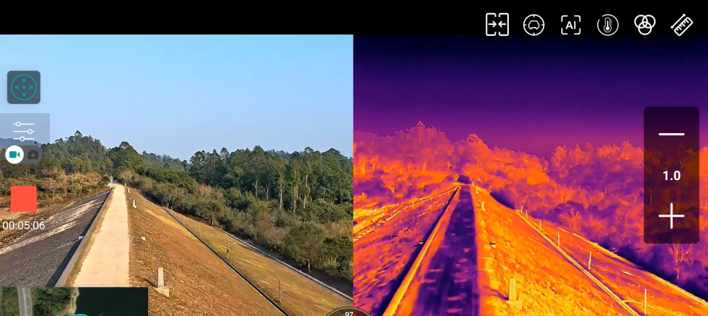
K40T thermal imaging interface showing the independent thermal view and measurement display.
A more reliable field workflow
Step 1: Observe with thermal imaging. Look for thermal differences among identical or comparable components and determine whether the image contains an anomalous pattern that deserves further inspection.
Step 2: Locate with infrared super-resolution fusion. Use the visible-light information added to the image to relate the thermal distribution to component structures, access routes and the surrounding environment. When necessary, adjust the fusion intensity gradually to achieve a suitable balance between the visibility of the thermal anomaly and structural detail.
Step 3: Switch to split screen for confirmation. Compare the two source images, check whether the anomaly genuinely exists in the thermal channel, and determine whether critical edges originate from thermal data, visible-light data or image processing. Also examine how the fields of view and target positions correspond between the two channels.
Step 4: Adjust the measurement display. Select the thermal palette, upper and lower temperature limits, and required measurement parameters according to the operating procedure. The fused image can assist with localization, but formal measurement results should remain traceable to the thermal channel and the correct source pixels.
Step 5: Preserve the evidence and field conditions. Depending on the task, retain the native thermal image, corresponding visible-light image or video, measurement metadata, and a fused or split-screen image that explains the location. Also record information such as distance, viewing angle, weather, time, equipment status, palette and fusion settings.
The emphasis placed on each stage can be adjusted for the mission. Security patrols prioritize rapid localization and may use fused imagery more often. Professional thermal inspections will generally review the independent thermal image first and then use split screen to verify the evidence. The display method should follow the decision that needs to be made at that moment.
To learn how wide-angle, telephoto and thermal cameras divide their roles in a complete inspection, see HEQ’s multi-sensor UAV inspection workflow.
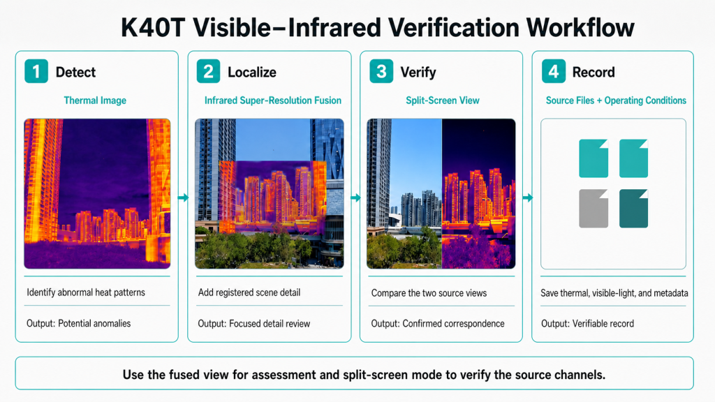
Field workflow using thermal imaging, infrared fusion and split-screen viewing.
What should be tested during a gimbal camera demonstration?
- Mode switching: Can the operator switch quickly among thermal, visible-light, fused and split-screen views?
- Image alignment: At the actual working distance, can the thermal anomaly remain acceptably registered with the visible-light structure?
- Performance in motion: Does the fused image remain stable and readable while the gimbal moves and the aircraft vibrates?
- Latency: Is the response speed of the live feed sufficient for the flight and inspection workflow?
- Image retention: Which source channels can be recorded, and can they be saved simultaneously?
- Thermal controls: Can the operator conveniently adjust the palette, upper and lower temperature limits, and measurement settings?
- Display environment: Does the image remain clear and usable on the actual controller or monitor under bright outdoor light?
- Reporting workflow: Can the recorded files and metadata meet the customer’s inspection or incident-reporting requirements?
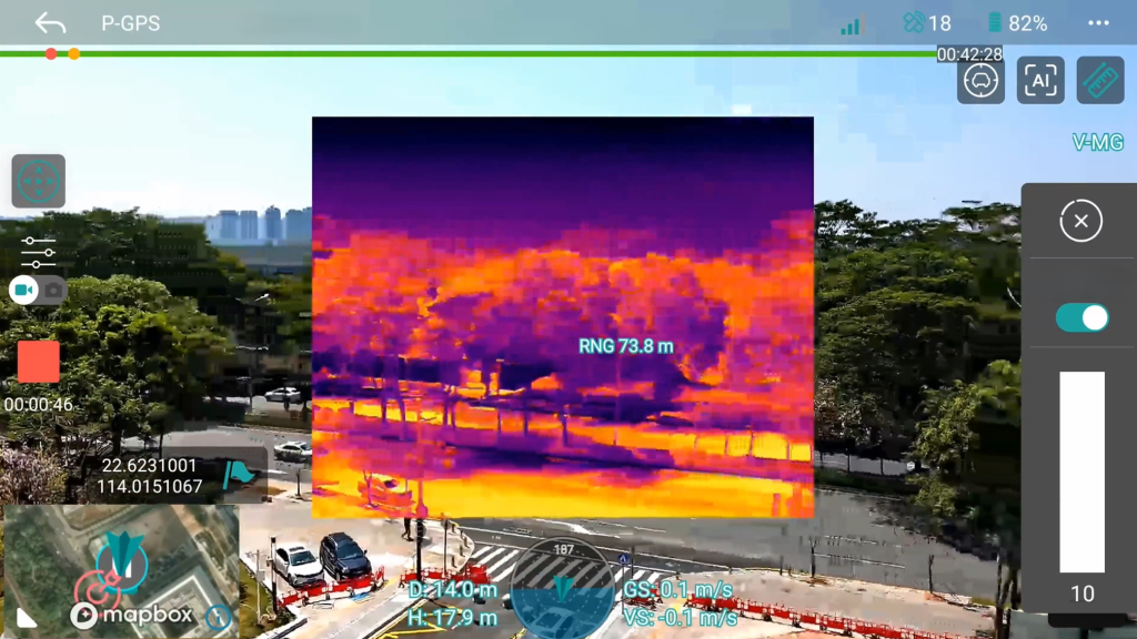
K40T infrared super-resolution fusion demonstration
Frequently asked questions
Is a fused image always better than a thermal image?
A fused image combines thermal-anomaly cues with visible scene details and is generally better suited to localization. A thermal-only view is more appropriate when thermal differences need to occupy a larger display area or when the operator needs to inspect the thermal source data without visible-light blending.
Does super-resolution turn a 640 × 512 detector into a native 1280 × 1024 detector?
No. Super-resolution uses interpolation and algorithmic enhancement to produce a larger processed image. The detector’s native resolution remains 640 × 512. This distinction is important when comparing gimbal-camera specifications and understanding measurement capabilities.
Why might edges in a fused image be slightly misaligned?
The two sensors use separate lenses with different physical positions and fields of view. Registration can compensate for some of these differences, but residual misalignment may become more noticeable when targets are close, scene depth changes or the image is moving.
Can fused screenshots be used in an inspection report?
A fused screenshot can clearly show the location of an anomaly. For technical analysis, the source thermal record, visible-light reference image and relevant metadata should also be retained. It is best to define the specific reporting requirements before the mission begins.
Technical references
- HEQ, K40T Quad-Sensor AI Gimbal Camera Specifications.
- J. Ma, Y. Ma and C. Li, Infrared and visible image fusion methods and applications: A survey, Information Fusion, 2019.
- R. Gade and T. B. Moeslund, Thermal cameras and applications: a survey, Sensors, 2014.
- J. Zhang et al., Infrared and Visible Image Fusion Technology and Application: A Review, Sensors, 2023.
Evaluate the K40T for your UAV workflow
If you are evaluating a multi-sensor payload for industrial inspection, patrol or another professional UAV application, share your target type, working distance, aircraft platform and required outputs with the HEQ Tech Team. We can help you determine whether the K40T fits your operational and integration requirements.