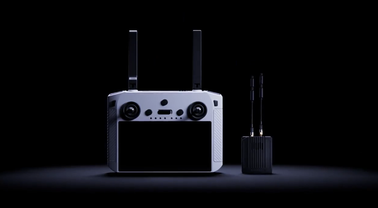
A UAV remote controller is easy to mistake for a sophisticated pair of joysticks. In an industrial drone system, however, it can sit at the center of four different information paths: flight control, drone telemetry, live video and payload interaction.
When buyers compare a drone remote controller, those paths can appear to be one feature because they may share radio hardware, antennas and an operator screen. They do not, however, carry the same information or serve the same purpose. A clear video feed does not prove that every payload command is available. A responsive control link does not guarantee that the operator is receiving the required telemetry. A 1080p display does not mean that the payload, transmitted stream and recording all use the same resolution.
For UAV integrators and procurement teams, the useful question is “How does the controller connect the operator to the drone, flight controller, payload and mission data—and which parts of that chain have been verified together?“
The short answer: one device, four system roles
| Path | Direction | What it carries | What the operator uses it for |
|---|---|---|---|
| Flight control | Ground to drone | Stick, switch and command inputs | Direct the drone or request a flight function |
| Telemetry | Primarily drone to ground, with some two-way commands | Position, attitude, battery, flight mode, link state and system messages | Understand drone condition and mission progress |
| Video | Payload or drone to ground | Encoded visible, thermal or other image streams | Observe, inspect, frame and document a target |
| Payload interaction | Two-way | Gimbal and camera commands plus payload status or metadata | Move the gimbal, select a sensor, zoom, capture data or activate supported functions |
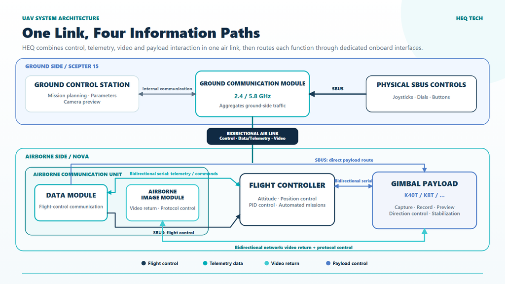
In the HEQ Nova architecture, remote control, data transmission and image transmission share one bidirectional link between the ground and airborne communication modules. Once onboard, the paths branch: the data-transmission module connects with the flight controller and can also provide an SBUS path to the payload, while the image-transmission module uses a bidirectional network connection with the gimbal camera for video return and supported protocol control. The exact interfaces and enabled functions still depend on the drone, payload, application and firmware combination.
1. Flight control: the controller sends intent, the UAV closes the loop
In the HEQUAV architecture, the joysticks, dials and buttons form a physical SBUS-control subsystem inside the handheld controller. These inputs enter the Scepter 15 ground communication module and cross the bidirectional radio link. The airborne data-transmission module then provides SBUS to the flight controller. The flight controller combines pilot intent with data from the IMU, GNSS, compass, barometer and other sensors to stabilize and control the drone.
This distinction matters: the remote controller normally does not command individual motors directly. It supplies inputs or higher-level commands to a flight-control system that manages the drone response.
A control-path review should confirm
- the receiver-to-flight-controller interface and electrical requirements;
- channel mapping, endpoints, direction and deadband;
- mode-switch logic and any arming controls;
- command update behavior and link-quality indication;
- what the UAV does when the link degrades or is lost;
- which settings are stored in the controller, receiver, autopilot or application;
- the exact firmware and configuration used during acceptance testing.
Failsafe behavior is an drone-level safety decision, not a feature to infer from the remote controller alone. The response may depend on the receiver, autopilot configuration, navigation state, operating area and applicable regulations.
2. Telemetry: the drone explains what it is doing
Telemetry gives the operator structured information about the vehicle and mission. Depending on the system, this can include position, altitude, attitude, speed, battery condition, flight mode, GNSS state, warnings and communication-link status. It is different from live video: telemetry describes vehicle state as data, while video represents a visual scene.
The MAVLink documentation, for example, describes continuous telemetry streams for information such as position, velocity and attitude. MAVLink can also carry commands and higher-level services, but naming a protocol is not enough to establish compatibility. Both endpoints must support the required messages, version, addressing, rates and command behavior.
In the Nova-4T system, the serial connection with the flight controller is bidirectional, allowing drone data to return toward the ground GCS while commands can travel toward the drone.
3. Video: the controller displays an image it did not create
The gimbal camera sensor captures the scene, while onboard electronics process and encode the imagery. The gimbal camera connects to the airborne image-transmission module through a bidirectional network interface. Video returns through this module and the ground-to-air link to the controller’s GCS application, where it can be previewed on the built-in display or passed to another display or recorder. The same network connection can carry supported protocol-control traffic toward the payload.
Because this is a chain, several resolutions and frame rates may be involved:
- sensor resolution describes the detector or image sensor;
- encoded-stream resolution and frame rate describe what leaves the drone-side encoder;
- received-stream quality depends on the encoder and communication link;
- display resolution and refresh rate describe the controller screen;
- recording resolution and bitrate describe the saved file.
The Scepter 15 has a 5.5-inch, 1920 × 1080 display with a 60 FPS refresh rate and maximum brightness of 1000 nits. It also lists 1080p HDMI output. These are controller display and output specifications. They won’t change the resolution of the content captured by gimbal camera sensors.
[UPLOAD DIAGRAM: HEQ-061-video-chain-en.png]
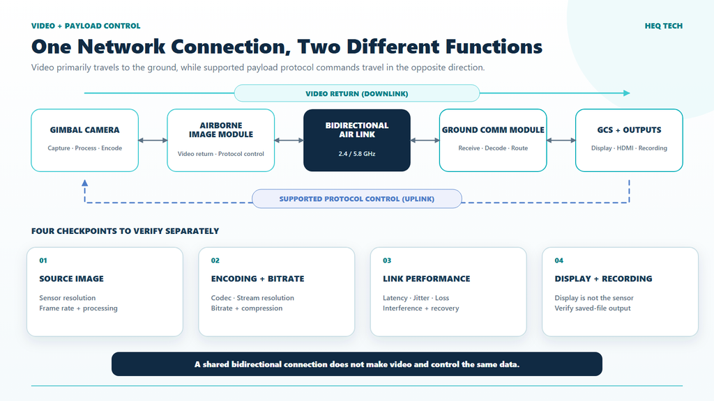
In the HEQ architecture, video return and supported payload protocol control share a bidirectional network path while remaining different functions.
4. Payload interaction: commands must reach the correct device
A multi-sensor payload adds another control layer. The operator may need to move the gimbal, switch between wide-angle, telephoto and thermal channels, adjust zoom, take a photograph, start recording, select a thermal palette, request a range measurement or use an available tracking function.
Each function needs an end-to-end path,:
Operator input → controller application → communication link → onboard interface → payload command → payload response
| HEQ payload-control route | Connection shown in the system diagram | Possible role |
|---|---|---|
| Direct SBUS route | Airborne data-transmission module → gimbal camera | Channel-based payload commands from physical controller inputs |
| Flight-controller route | Flight controller ↔ serial ↔ gimbal camera | Commands or status exchanged through the UAV control system |
| Network protocol route | Image-transmission module ↔ network ↔ gimbal camera | Video return together with supported bidirectional payload protocol control |
Control ownership also matters. A gimbal may receive requests from a pilot, an automated mission, a tracking process or a companion computer. The system needs a defined method for deciding which source is in control.
What the remote controller is—and what it is not
| Component | Primary responsibility | Common misunderstanding |
|---|---|---|
| Physical controller inputs | Convert joystick, dial and button actions into SBUS control inputs for the ground communication module | The GCS touchscreen and physical controls are one undifferentiated command source |
| Ground-control application | Support mission planning, parameter settings, camera preview and the operator workflow | A compatible operating system guarantees every application and payload function |
| Ground communication module | Exchange remote-control, data and image-transmission traffic with the airborne communication unit | Each logical function must use a separate radio |
| Airborne data-transmission module | Connect the radio link to flight-control communication and SBUS control paths | It carries only joystick commands |
| Airborne image-transmission module | Exchange camera video and supported protocol-control traffic over a network connection | Image transmission is necessarily a one-way video-only path |
| Flight controller | Stabilize and navigate the UAV according to configured logic and received commands | It is simply a relay between joysticks and motors |
| Payload | Capture, process and output mission sensor data; execute supported camera and gimbal commands | The ground controller creates or improves the source imagery by itself |
Scepter 15 in the Nova-4T system
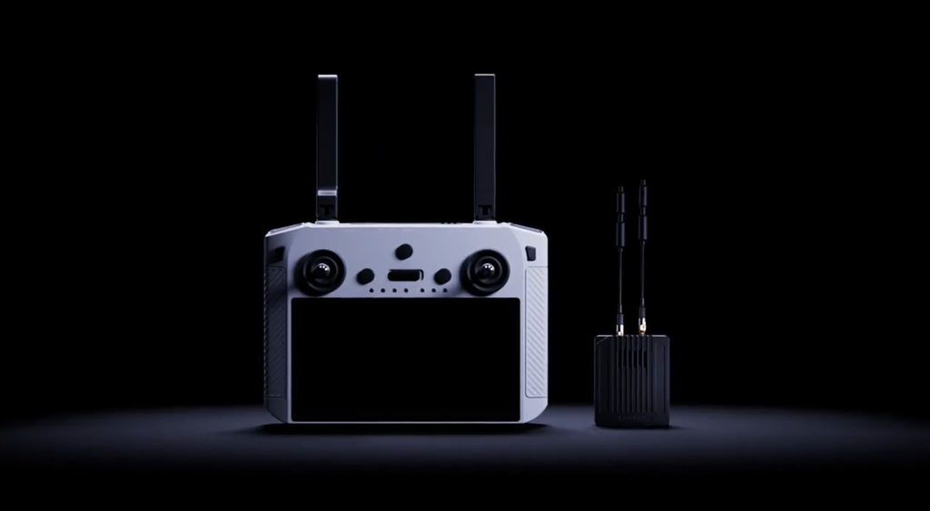
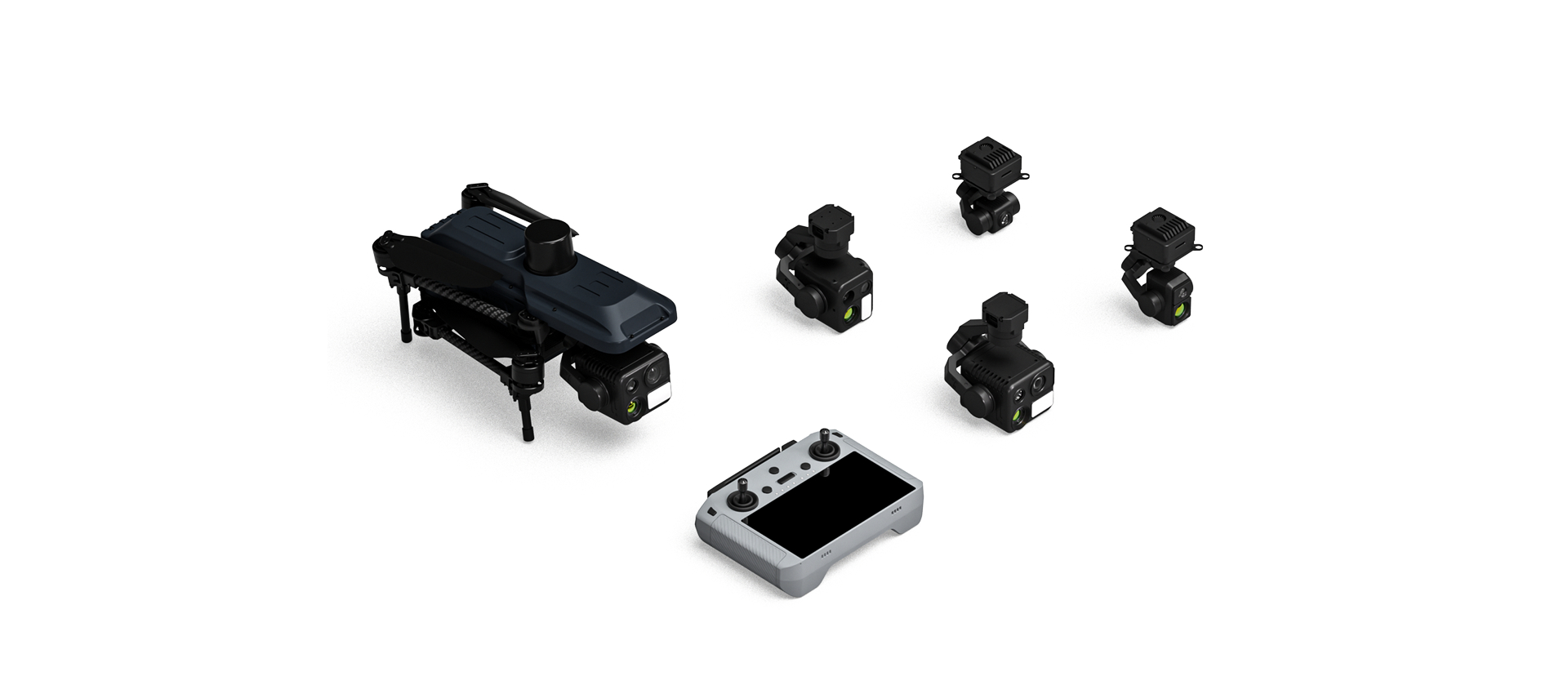
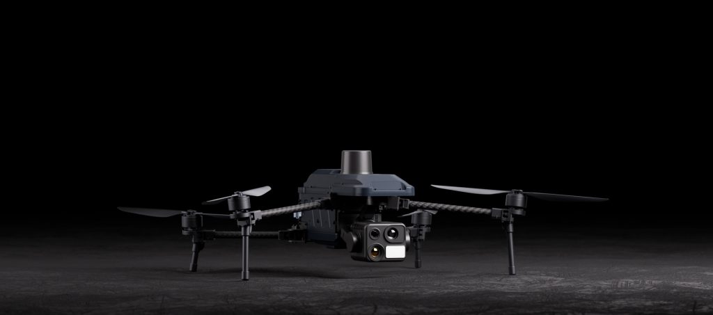
The Nova-4T is a useful example because it combines a UAV platform, the K40T quad-sensor gimbal camera, the Scepter 15 remote controller. The whole system contains airborne communication unit with distinct data-transmission and image-transmission functions. The table below summarizes its controller-related values
| Area | Published specification | Integration meaning |
|---|---|---|
| Image-transmission radio | Dual antenna; 2.4 GHz + 5.8 GHz; maximum effective signal range 15 km | Component-level radio information; field performance still depends on the complete system and test conditions |
| Nova-4T system transmission | 10–12.5 km, FCC, unobstructed | Integrated-system figure with stated regional and line-of-sight conditions |
| Display | 5.5 inches; 1920 × 1080; 60 FPS; maximum brightness 1000 nits; five-point multi-touch | Defines the local viewing interface, not the payload sensor or transmitted-stream specification |
| Output and storage | 1080p HDMI; TF-card external storage | Supports an external-display or storage workflow, subject to application and stream configuration |
| Controller system | Android 11; 4 GB RAM + 32 GB storage | Defines the computing environment; required application and version must still be confirmed |
| Controller battery | 5000 mAh; 4.5-hour operating time; PD 30 W charging; 1.5-hour charging time when powered off | Helps plan a shift, but real endurance should be checked under the actual display, radio and environmental load |
| Controller environment | IP53; −10°C to 45°C; 700 g | Supports handling and environmental planning; it does not define the protection rating of the drone or payload |
| Airborne communication unit | 16-channel SBUS; UART data connection; network and USB interfaces; 12–27 V input; 50 g without atenna | Contains distinct data and image paths in the HEQ system architecture; pinout, data settings and function mapping still require documentation |
Why maximum range is not the same as usable mission range
A maximum signal-range specification is usually established under defined conditions. Buildings, terrain, vegetation, antenna orientation, interference, frequency configuration, data rate, UAV attitude and regulatory power limits can all change real link performance.
Different functions may also stop being useful at different points. The pilot might still receive basic telemetry while a high-bitrate video stream becomes unstable. Video may remain visible but too delayed or compressed for close inspection. A payload command may be sent without sufficiently clear feedback that it was executed. This is why a single “range” number cannot replace a function-by-function link test.
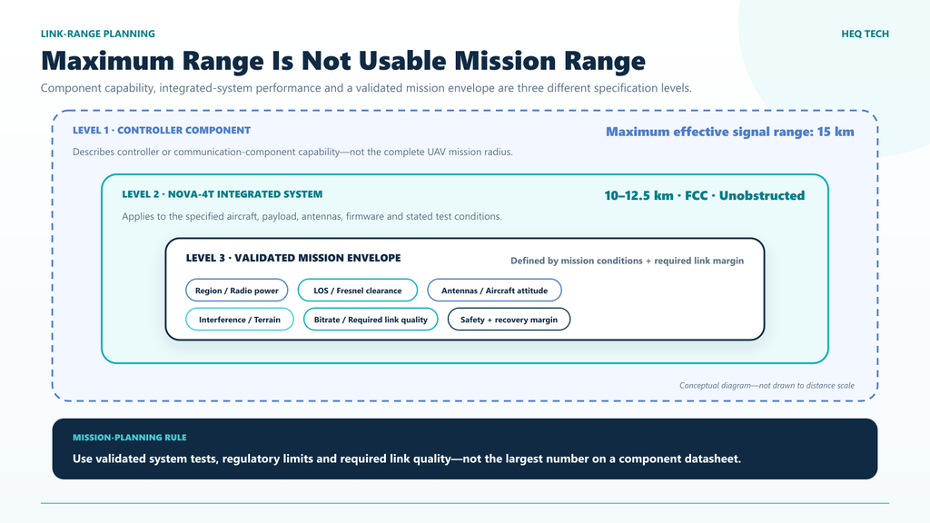
Plan missions around the validated system envelope, not the largest component-level distance on a specification sheet.
A practical controller-selection checklist
A professional drone remote controller should be selected as part of the complete unmanned system. The following checks turn broad product claims into requirements that can be documented and tested.
1. Start with the operator’s decisions
List what the operator must see and control during the mission. An inspection workflow may require drone position, live wide-angle context, telephoto confirmation, thermal viewing, measurement status and recording controls. A simpler survey UAV may need a different interface. Select the controller around the workflow rather than around an isolated range number.
2. Map every required function end to end
Create a matrix with one row per flight or payload function. Identify the operator control, ground application, radio path, receiver output, onboard destination, protocol message and expected feedback. Mark any function that depends on a specific firmware or application version.
3. Separate control, telemetry and video requirements
Specify the required command behavior, telemetry items and update rates, video channels, stream resolutions, frame rates, bitrate, latency, recording and external outputs separately. This makes omissions visible and gives the supplier a testable acceptance target.
4. Check the physical controller and receiver
- screen size, brightness and readability in the intended environment;
- battery duration and charging workflow for the expected shift;
- controller weight, controls and operation with gloves if required;
- HDMI, storage and data-export needs;
- receiver mass, input voltage, connectors, antenna placement and cooling;
- environmental limits for both ground and airborne equipment.
5. Define the radio test conditions
Record the regulatory configuration, frequency mode, antennas, antenna orientation, altitude, route, terrain, obstruction, interference, weather, video settings and required link margin. Test the complete system that will be delivered—not a controller and receiver isolated from the actual UAV and payload.
Acceptance tests before operational use
- Bench connection: verify receiver voltage, polarity, pinout, antennas and all physical connections.
- Control mapping: confirm every stick, switch and channel direction with propulsion made safe.
- Telemetry: compare displayed values with known or independently checked values and confirm warning behavior.
- Video: verify each required sensor channel, stream, recording and HDMI output under the intended settings.
- Payload functions: test gimbal movement, channel switching, zoom and every other contracted function; confirm both action and feedback.
- Link degradation: evaluate link-quality indication, video behavior, command response and recovery according to approved test procedures.
- Failsafe: validate the aircraft response under the manufacturer’s safety process and applicable regulations.
- Field configuration: repeat the test using the production aircraft, payload, antennas, firmware, application and regional settings.
A controller is ready for service only when the complete system behaves predictably. A bench test proves basic integration; it does not replace a controlled flight-test program.
Frequently asked questions
Is a UAV remote controller the same as a ground control station?
Not always. A handheld controller may run ground-control software and combine physical controls, a display and communication hardware in one device. In other architectures, the ground-control application runs on a separate computer connected to radio equipment. Define both the hardware and software when comparing systems.
Does a 15 km controller specification mean the UAV can be operated at 15 km?
No. A component range is not permission or a guarantee for a mission. The complete UAV system, antennas, environment, required link quality, battery endurance, operating procedures and regional regulations all affect the permitted and usable mission envelope.
Does a 1080p controller screen mean the payload transmits 1080p video?
No. Screen resolution describes the display. Sensor resolution, encoded-stream resolution, received image quality and recording resolution are separate specifications. Confirm each stage of the video chain.
If two systems use 2.4 GHz and 5.8 GHz, are they compatible?
No. Frequency bands alone do not define the waveform, pairing, channel plan, protocol, security, power configuration or application compatibility. Use the transmitter and receiver combination approved by the supplier for the system.
Does MAVLink support make a payload plug-and-play?
Not by itself. The products still need compatible MAVLink versions or dialects, messages, component addressing, transport settings and application support. High-bandwidth video may use a separate path. Confirm the exact tested functions rather than relying on the protocol name.
Technical references
- HEQ UAV Tech, Nova-4T and Scepter 15 specifications.
- HEQ UAV Tech, software and document download center.
- MAVLink, protocol overview and general telemetry.
- MAVLink, Gimbal Protocol v2.