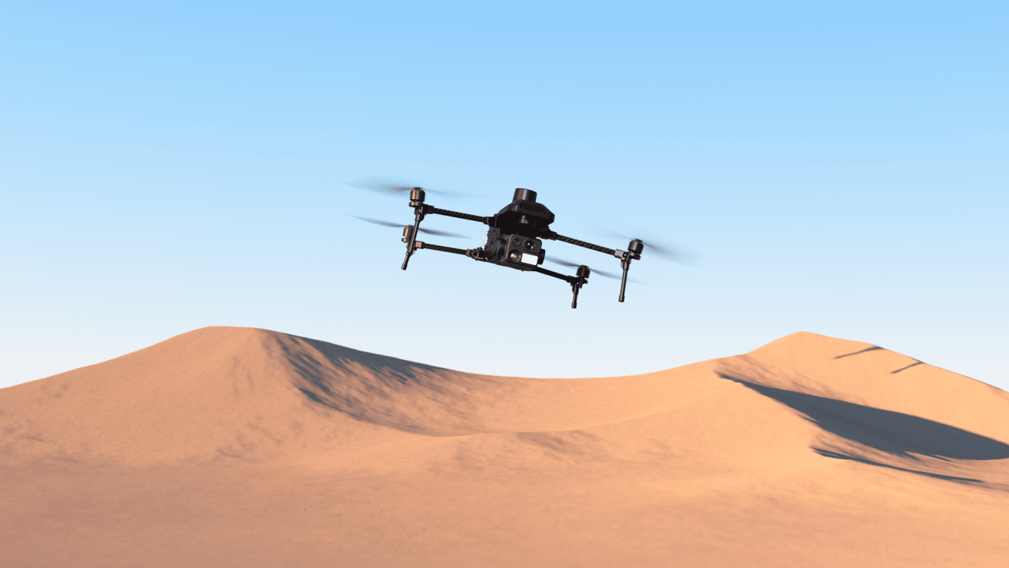
A camera payload can meet every imaging requirement and still be the wrong choice for an UAV platform. If its weight shifts the center of gravity, its startup current exceeds the available power rail, its video cannot pass through the data link, or its control commands are not implemented by the flight stack, the integration is incomplete.
For UAV OEMs, solution providers and procurement teams, payload selection therefore needs two parallel checks: Can the sensor produce the required information? And can the complete UAV system carry, power, control, transmit and protect it?
This guide explains how to evaluate payload weight, power, IP rating, physical interfaces and communication protocols as one integration system. It also uses current HEQ gimbal specifications to show why products with similar voltage and connector options can still require different engineering decisions.
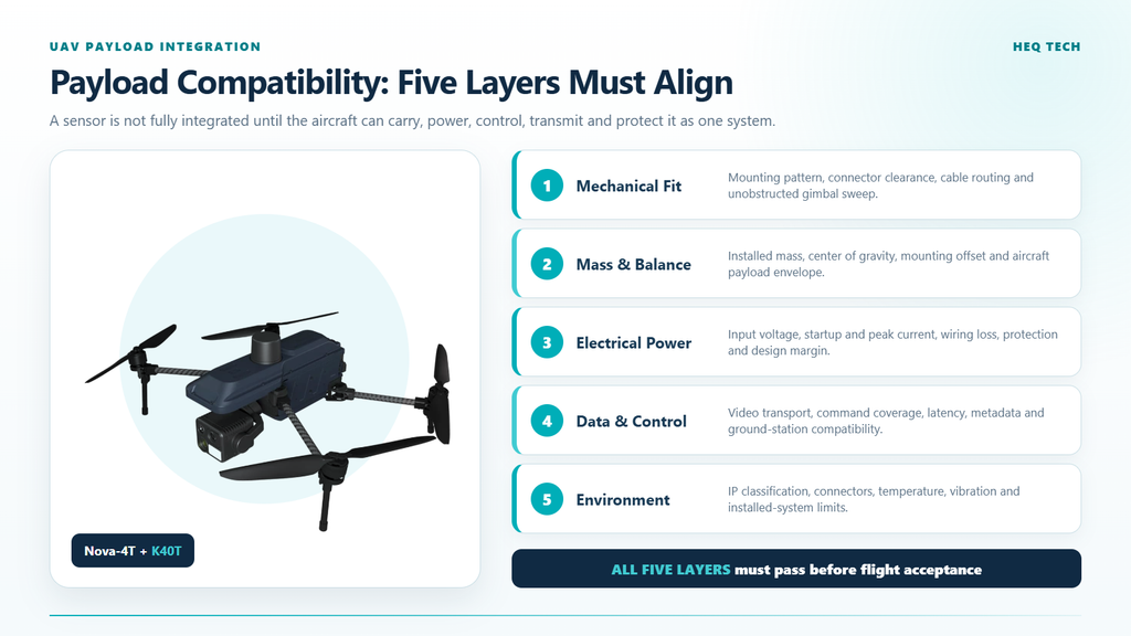
A payload is compatible only when every integration layer works together.
The short answer: compatibility is a chain
| Integration layer | Question to answer | Evidence to request |
|---|---|---|
| Mechanical | Does the payload fit, move freely and remain rigidly mounted? | Envelope drawing, mounting pattern, connector-clearance drawing and gimbal sweep model |
| Mass and balance | Can the UAV carry the mass at its actual mounting position? | Payload mass, center-of-gravity location, mounting offset and drone payload-envelope data |
| Electrical | Can the power rail supply the correct voltage and current under all operating states? | Voltage range, nominal and peak power/current, startup behavior, connector pinout and protection requirements |
| Data and control | Can the pilot, autopilot and ground station command the functions and receive the required video/data? | Interface specification, protocol document, supported commands, stream format, bitrate and latency test |
| Environmental | Does the installed system tolerate the expected temperature, dust, moisture and vibration? | IP classification, operating limits, test conditions and installed-system validation |
A pass at one layer cannot compensate for a failure at another. Ethernet video does not solve an overloaded power rail. A low payload mass does not solve an obstructed gimbal. MAVLink support does not guarantee that every camera or gimbal function appears automatically in a particular ground-control application.
1. Payload weight is more than a number in grams
The payload mass is the starting point, not the complete loading case. The UAV also carries vibration isolators, wiring, connectors and any interface or companion-computer hardware required for integration. These items should be included in the installed payload mass.
Mounting position matters as much as total mass. A payload located away from the drone’s designed center of gravity creates a moment that the flight-control system and propulsion system must manage. A forward or downward offset can affect balance, control authority, motor loading and landing clearance even when the nominal payload capacity has not been exceeded.
Payload moment = installed mass × distance from the reference point
This simple relationship explains why two payloads of the same mass may not be interchangeable. Their mounting brackets, centers of gravity and cable routing may place the load in different positions.
The gimbal also needs an unobstructed movement envelope. Check the full pitch, roll and yaw range against landing gear, arms, antennas and the airframe. Repeat the check with the actual connector and cable bend radius. A cable that looks clear in the neutral position may tighten, rub or enter the camera view at the edge of travel.
What to verify before the first flight
- installed mass, including mount, wiring and adapters;
- payload center of gravity relative to the drone reference;
- mounting-hole pattern and fastener specification;
- connector orientation, strain relief and service access;
- full gimbal sweep without airframe collision or camera occlusion;
- landing clearance in normal and abnormal gimbal positions;
- vibration-isolator suitability for the drone and payload mass range;
- revised drone’s center of gravity and flight-envelope approval.
2. Power compatibility requires voltage, current and margin
A payload specification often lists an operating-voltage range and nominal power consumption. Both are necessary, but neither alone is enough to size the UAV power output.
The voltage supplied at the payload connector must remain within the approved range during startup, gimbal movement, camera processing, recording and other high-load states. Cable resistance, connector losses and shared loads can cause voltage at the payload to be lower than voltage measured at the power-distribution board.
Estimated input current = power ÷ voltage
As an initial estimate, a 12 W payload would draw 1 A at 12 V or approximately 0.67 A at 18 V if it behaved as an ideal constant-power load. That calculation is useful for an early power budget, but it is not a substitute for the manufacturer’s peak-current and startup-current data. Real current varies with conversion efficiency and operating state.
Power design should include margin rather than sizing the rail exactly to the published nominal value. The required margin depends on the UAV architecture, the certainty of the peak-load data, other devices on the same rail and the consequences of a voltage drop. Confirm overcurrent protection, polarity protection, grounding, connector ratings and whether the supply is isolated or shares noise with motors and radios.
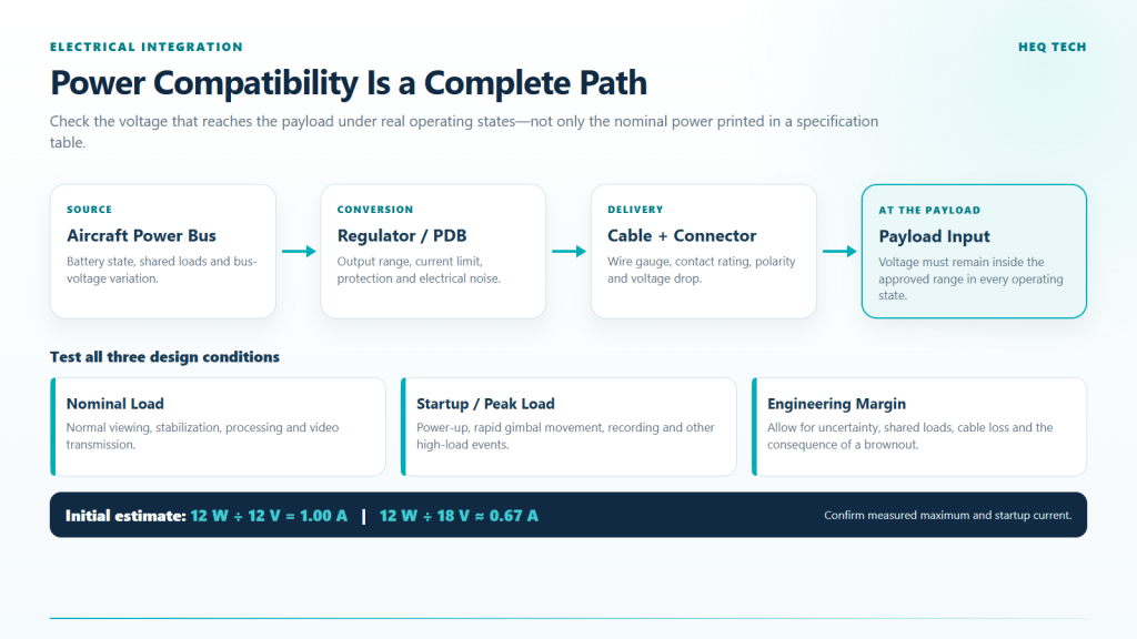
Size the payload power path for voltage at the connector and peak operating states, not nominal watts alone.
Power questions for the supplier
- What are the minimum, nominal and maximum input voltages?
- What are the nominal, maximum and startup current values?
- Under which camera, recording, heating or gimbal conditions were they measured?
- What connector, pinout and wire gauge are recommended?
- Is reverse-polarity, overvoltage or overcurrent protection built in?
- What happens after a brief brownout: automatic restart, latched fault or manual reset?
- Does the payload require a shutdown sequence before drone power is removed?
3. IP rating describes an enclosure test, not the whole mission
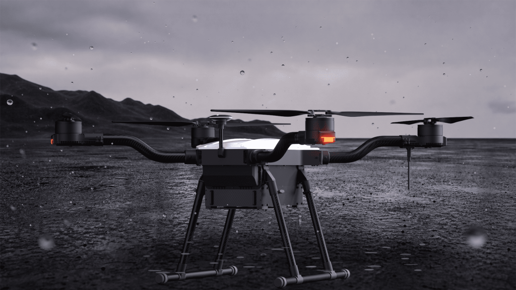
Ingress-protection classifications are defined by IEC 60529. In an IP code, the first characteristic numeral relates to protection against access and solid foreign objects, while the second relates to water ingress. An IP rating is valuable procurement information because it provides a standardized enclosure classification.
It should not be interpreted as a general promise that the complete UAV is weatherproof. The classification applies to the enclosure and test configuration that were evaluated. The installed system may include exposed connectors, an adapter plate, a quick-release mount, cable entries and an drone body with different protection levels.
Operating-temperature range and IP rating also describe different limits. A payload can meet its temperature specification and still require protection from rain, condensation or dust. Conversely, an enclosure rating does not prove image quality, stabilization performance or battery endurance at the edge of the temperature range.
Ask what was actually tested
- Which product version and connector configuration received the stated rating?
- Were protective caps, seals or a specific mounting plate required?
- Does the classification apply while the gimbal is moving?
- What inspection or maintenance is required after exposure?
- Which component becomes the weakest environmental link after installation?
4. Interfaces and protocols are different layers
An interface describes how systems are physically or electrically connected and how data is transported. A protocol defines the structure and meaning of the information exchanged. Procurement specifications often mix these layers, which creates avoidable integration surprises.
| Term | What it tells you |
|---|---|
| Ethernet / network interface | A network connection is available for data transport |
| Serial / TTL | A serial electrical/control connection is available |
| SBUS | A channel-based control input is available |
| H.264 / H.265 | The payload can encode video using these compression formats |
| MAVLink | The product implements some MAVLink communication |
MAVLink’s official documentation describes it as a lightweight messaging protocol for communication with drones and between onboard components. Its common message set includes camera and gimbal services, but products can implement different subsets or use custom dialects. Therefore, a specification that says “MAVLink supported” is the beginning of an integration discussion, not the end.
For gimbal control, confirm whether the payload and flight stack use the same control model, messages and reference frames. The current MAVLink Gimbal Protocol v2 distinguishes the physical gimbal device from the gimbal manager that coordinates commands from the pilot, mission, autopilot or companion computer. A payload may support MAVLink without exposing every function through that standard gimbal service.
Video should be evaluated as a separate path. MAVLink commands may control the gimbal while an Ethernet stream carries H.264 or H.265 video. The system still needs compatible addressing, stream discovery, decoding, bandwidth and latency. If metadata must be synchronized with imagery, define how timestamps, UAV position, gimbal attitude and camera events are recorded.
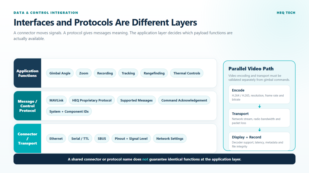
A shared connector or protocol name does not guarantee identical functions at the application layer.
What a protocol compatibility matrix should contain
- physical connector and pinout;
- electrical level, baud rate or network settings;
- protocol version and dialect;
- system ID and component ID behavior;
- supported gimbal angle, rate, recenter and mode commands;
- supported zoom, focus, palette, recording, tracking and ranging commands;
- status and telemetry messages returned by the payload;
- command acknowledgement and retry behavior;
- video transport, codec, resolution, frame rate and bitrate;
- tested autopilot, firmware and ground-control-software versions.
Current HEQ payload examples
The following published specifications illustrate how integration requirements vary across payloads. They are not a substitute for the connector drawing, protocol document or drone-level test.
| Payload | Published weight | Input voltage | Power | Published interfaces | Published protocol | IP rating |
|---|---|---|---|---|---|---|
| K8T-V3 | 147 g ±5 g | 12–18 V | 8 W | Ethernet / serial / SBUS | HEQ proprietary / MAVLink | IP44 |
| K11 | 195 g ±5 g | 12–18 V | 12 W | Network / TTL / SBUS | HEQ proprietary / MAVLink | IP54 |
| K40T Mini | 267 g ±5 g | 12–18 V | 12 W | Ethernet / serial / SBUS | HEQ proprietary / MAVLink | IP54 |
| K40T | 290 g ±5 g | 12–18 V | 12 W | Ethernet / serial / SBUS | HEQ proprietary / MAVLink | IP54 |
Several observations follow from the table. First, a common 12–18 V input range does not make the products mechanically interchangeable. Their masses, sensor configurations and mounting effects differ. Second, the lighter K8T-V3 also lists lower nominal power, but its IP rating and published protocol differ from those of the K40T. Third, similar interface labels do not confirm identical connectors, pinouts or command coverage. Those items belong in the integration package for the specific product version.
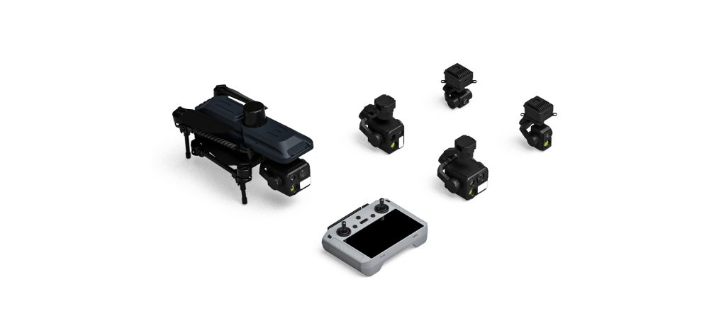
A six-stage payload integration workflow
Stage 1: Define the mission output
Specify what the operator and downstream customer need: live viewing, thermal measurement, long-range detail, target coordinates, synchronized recording, automated tracking or another deliverable. This prevents teams from integrating functions that do not support the mission while overlooking essential data paths.
Stage 2: Freeze the mechanical configuration
Select the orientation, isolation system and cable route. Confirm the installed mass and center of gravity, not the camera weight alone. Review the gimbal movement envelope in CAD and then on the physical airframe.
Stage 3: Complete the electrical budget
Document source voltage, regulator capacity, peak load, shared loads, cable loss, protection and margin. Bench-test startup and worst-case functions at both ends of the approved input range before connecting the payload to the flight system.
Stage 4: Build the interface and command matrix
Map every required function to its connector, transport, protocol message and application control. Record which device owns gimbal control and how conflicts between manual input, missions, tracking and companion-computer commands are resolved.
Stage 5: Validate the complete data path
Test the live stream on the actual radio, ground station, display and decoder. Measure usable latency, dropout recovery and recording integrity. Confirm that metadata and source channels required by the final report are preserved.
Stage 6: Conduct ground and flight acceptance tests
Begin with restrained or low-risk ground testing, then expand the flight envelope gradually. Include gimbal extremes, maximum zoom, recording, tracking, low link quality, power cycling and expected environmental conditions. Record UAV performance before and after installation so the payload’s effect can be evaluated rather than assumed.
Questions to put in the payload request for quotation
- What is included in the stated payload weight, and where is its center of gravity?
- Can you provide a dimensional drawing, mounting pattern, connector drawing and 3D model?
- What are the nominal and peak power/current values, including startup?
- What cable, connector and protection requirements apply?
- Which product configuration received the stated IP rating?
- Which physical interfaces are available, and what are their electrical specifications?
- Which MAVLink version, dialect, messages and services are implemented?
- Which functions require the HEQ proprietary protocol?
- How are video, metadata and control transported and synchronized?
- Which autopilot, ground station and firmware combinations have been tested?
- What documentation, SDK, sample code and integration support are included?
- What ground and flight acceptance tests does the supplier recommend?
Frequently asked questions
Does staying below the UAV’s maximum payload capacity guarantee compatibility?
No. The drone must also remain within its center-of-gravity, mounting, power, control and flight-envelope limits. The installed payload includes brackets, cables and interface hardware, and its position affects the drones differently from a centered test mass.
Can flight time be calculated from payload watts alone?
No. Payload electrical consumption is only one part of the energy budget. Added mass and aerodynamic drag can change propulsion power, which is usually a major contributor to total drone energy use. A reliable endurance estimate requires drone-specific flight testing or a validated performance model.
Does an IP54 payload make the UAV safe to fly in rain?
Not by itself. The rating applies to a tested enclosure configuration. The UAV, mount, connectors, cables and other components may have different limits. Flight in precipitation must follow the UAV manufacturer’s limits, operating procedures and applicable regulations.
Does MAVLink support mean the gimbal is plug-and-play?
Not necessarily. Both sides still need compatible transport settings, protocol versions or dialects, messages, command behavior, component addressing and ground-station support. Video transport may also use a separate network path. Confirm the exact tested configuration and required functions.
Is Ethernet enough for both video and control?
It can carry multiple kinds of network traffic, but the product documentation must identify which streams and control services are implemented. Ethernet availability alone does not specify the video protocol, addressing, command interface, bandwidth or latency.
Technical references
- HEQ product specifications: K40T, K40T Mini, K8T-V3 and K11.
- MAVLink, MAVLink Developer Guide.
- MAVLink, Gimbal Protocol v2.
- IEC, IEC 60529: Degrees of protection provided by enclosures (IP Code).
Send HEQ your platform specifications
Choosing the sensor is only the first step. Send the HEQ Tech Team your UAV payload limit, mounting constraints, available voltage and current, autopilot, control interface, video-link requirements and mission outputs. We can help you identify the documentation and payload configuration required for an integration review.