A thermal camera can show a clear hot spot without measuring the true surface temperature of a selected object. The detector receives infrared radiation emitted and reflected by the scene, together with the influence of the atmosphere between the scene and the lens. The camera converts that combined signal into a thermal image.
The drone changes distance and viewing angle continuously, outdoor weather changes the scene itself, and many industrial assets contain polished metal, glass, paint, insulation and composite surfaces in the same view. A thermal pattern can therefore look clear while its physical cause—and any attempted estimate of object-surface temperature—remains uncertain.
This guide explains the four limitations that most often change drone thermography results—emissivity, reflectivity, weather and viewing angle—and shows how to turn them into a repeatable inspection workflow.
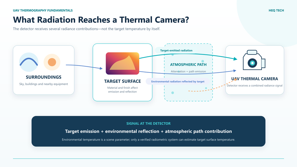
The detector receives a combined radiance signal. The environmental-temperature setting describes scene conditions.
A thermal image is evidence, not an automatic diagnosis
| Factor | What it changes | Common false conclusion | Field control |
|---|---|---|---|
| Emissivity | How strongly the surface emits its own thermal radiation | A sharp thermal image proves the object’s true temperature | Identify the material and surface condition; use a validated emissivity value or reference method when quantitative measurement is separately supported |
| Reflectivity | How much surrounding radiation is redirected toward the camera | A bright area must be a hot component | Look for reflection sources and repeat from another controlled angle |
| Weather and atmosphere | The target’s physical temperature, thermal contrast and transmission path | Results from different days can be compared without normalization | Record sun, cloud, wind, precipitation, humidity, ambient temperature and recent conditions |
| Viewing angle | Apparent emissivity, reflected scene, target footprint and pixels on target | A shallow-angle observation is equivalent to a near-normal view | Work as close to perpendicular as practical and keep geometry consistent |
1. Thermal imaging, environmental-temperature settings and object-temperature measurement are different
A thermal detector converts infrared radiation within its spectral band into an image. The brightness or color of a pixel represents the signal assigned to that location after calibration and image processing. This makes thermal cameras effective for finding spatial patterns: a roof area that cools differently from its surroundings, or a person that contrasts with a cooler background.
A calibrated radiometric system that supports object-temperature measurement adds another step: it estimates surface temperature from the received radiance after accounting for parameters such as emissivity, reflected apparent temperature, distance, atmospheric temperature and relative humidity.
Conceptual received signal = transmitted target emission + transmitted reflection + atmospheric contribution
This is why detector resolution and object-temperature accuracy are not interchangeable. Resolution determines how the thermal scene is sampled. Where calibrated radiometric measurement is supported, measurement accuracy describes how closely a properly configured system can estimate surface temperature under stated conditions. A high-resolution detector or an environmental-temperature setting does not establish that capability.
2. Emissivity: the surface controls how much of its own radiation you see
Emissivity describes how effectively a real surface emits thermal radiation compared with an ideal blackbody at the same temperature. It is not simply a material name. Surface finish, oxidation, paint, contamination, moisture, wavelength, temperature and viewing direction can all matter.
Many painted, oxidized or non-metallic surfaces have relatively high emissivity and are easier to interpret—and, with separately verified radiometric equipment, easier to measure—than clean, polished metals. A shiny conductor or stainless-steel enclosure can have low emissivity and high reflectivity. In that case, a large part of the signal reaching the camera may describe the surroundings rather than the metal itself.
An emissivity table is a starting point, not proof. The table may refer to a different alloy, surface treatment, temperature or spectral band. A high-emissivity reference patch can help in a controlled ground test when it is safe, permitted and allowed to reach the same temperature as the underlying surface.
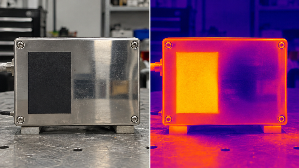
Illustrative comparison: Two areas on the same component can appear different in a thermal image because their surface properties change the emitted and reflected radiation.
Practical emissivity checks
- Record the target material, coating, finish, oxidation and contamination.
- Confirm whether the mission needs qualitative anomaly screening or verified object-surface temperature measurement.
- Do not treat the environmental-temperature setting as an object-temperature reading.
- Use only the measurement functions and parameters verified for the actual camera, application and firmware.
- Keep the target large enough in the thermal frame for the selected analysis or measurement tool.
- Do not transfer one emissivity value across visibly different surfaces without justification.
- Retain the original thermal data and parameter record when the workflow supports it.
3. Reflectivity: a thermal hot spot may belong to the surroundings
For an opaque surface, lower emissivity generally means a greater proportion of reflected infrared radiation. A polished metal target can behave like a thermal mirror. It may reflect the sky, sun-warmed structures, nearby machinery, the ground, the aircraft or the operator. The reflection can move or disappear when the camera changes position even though the target temperature has not changed.
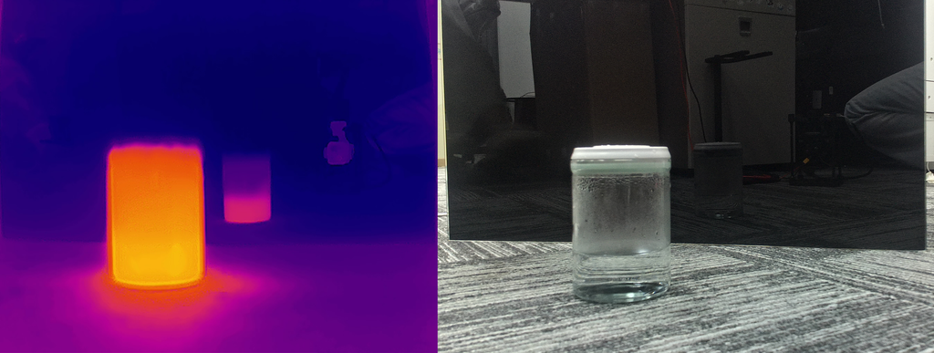
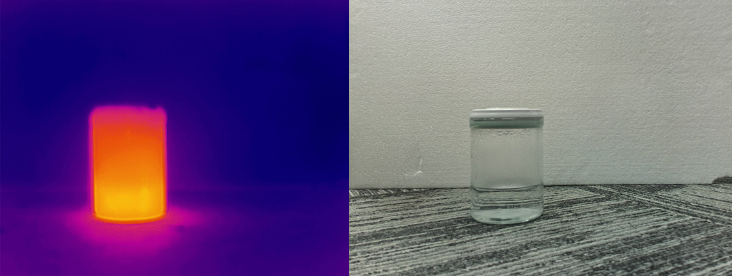
This creates two opposite risks. A cool sky reflection can make a surface appear colder than it is. A warm roof, wall or piece of operating equipment can create a false hot area. The problem is especially difficult when the reflection resembles the size and shape of a real component.
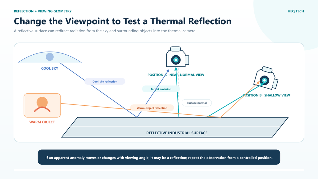
Changing the viewing position changes the reflected scene and can help separate a surface anomaly from a reflection.
A simple reflection test
- Hold distance, focus, thermal range, palette and span as constant as practical.
- Capture the suspected anomaly from the planned inspection angle.
- Move to a second safe angle while keeping the same target area in view.
- Observe whether the apparent hot or cold pattern moves across the surface or changes with the reflected background.
- Compare with adjacent phases, components or known references under similar load.
- Escalate uncertain results for ground confirmation rather than classifying the reflection as a fault.
This test is diagnostic, not absolute. A real anomaly can also change appearance with angle because the projected target area and intervening geometry change. Use the complete evidence set rather than one frame.
4. Viewing angle changes both radiometry and spatial sampling
A near-normal view looks toward the target approximately perpendicular to its surface. As the view becomes more oblique, several effects occur at once:
- the apparent emissivity of some surfaces can change;
- the camera sees a different reflected environment;
- the target occupies a smaller projected area;
- each detector pixel covers a longer footprint across the surface;
- edges, fasteners or nearby structures can mix into the measurement area;
- the gimbal or aircraft may partially block the intended line of sight.
For repeatable measurements, view the surface as close to perpendicular as the asset, airspace and safety plan allow. More importantly, use a consistent angle when trending the same component over time. A result collected at 20 degrees from the surface normal should not be treated as directly comparable with one collected at a grazing angle unless the method accounts for the difference.
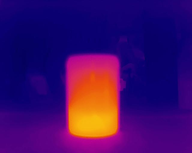
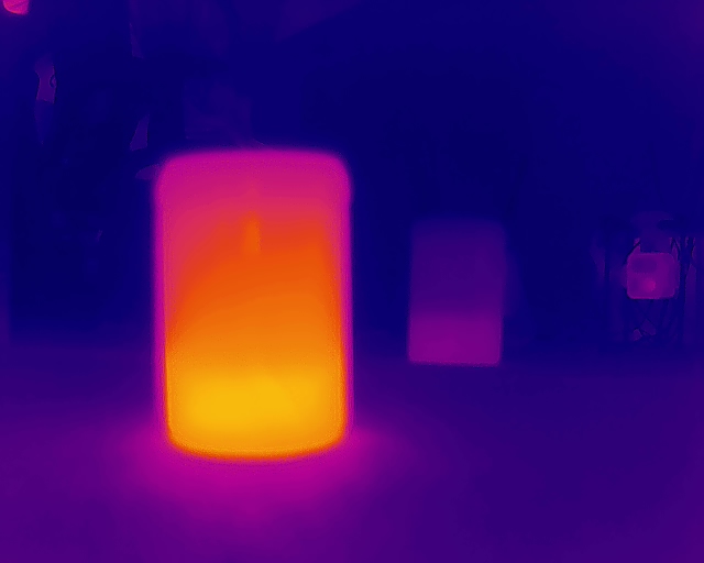
The same target should be checked at controlled angles because reflections, apparent emissivity and pixels on target can change together.
5. Weather changes the target before it changes the camera
Outdoor thermography is not performed in a thermal laboratory. Sun, wind, water, clouds and ambient temperature change how the asset gains, stores and loses heat. They can strengthen a useful temperature difference, suppress it or create a pattern unrelated to the fault being investigated.
Solar loading and changing cloud
Direct sunlight heats surfaces according to color, finish, orientation, mass and exposure history. A sunlit roof, enclosure or solar-module frame may remain warmer after it enters shade. Passing clouds can therefore change the scene faster than the asset reaches thermal equilibrium. The result may resemble an internal heat source even when it is external solar loading.
Record whether the surface is in sun or shade and note the recent sky condition, not only the condition at the instant of capture. Where the application allows, use a repeatable time window and compare equivalent surfaces with similar orientation and exposure.
Wind and convective cooling
Airflow removes heat from exposed surfaces. Strong or variable wind can reduce the temperature difference produced by a defect, cool one side of an asset differently from another and make repeated passes difficult to compare. There is no single wind threshold that fits every target. The useful limit depends on heat flow, target size, load, surface exposure and the decision being made.
Rain, dew and wet surfaces
Water can cool a surface through evaporation, redistribute heat and change its apparent surface properties. Rain, mist or droplets between the camera and target can also reduce contrast and contaminate the lens or protective window. An enclosure rating describes equipment protection under stated tests; it does not prove that thermal measurements collected in rain are valid.
Humidity, fog and atmospheric path length
The atmosphere absorbs and emits infrared radiation. Distance, humidity, atmospheric temperature and suspended water become more important as the path length increases. A long-range UAV observation therefore needs more than a clear line of sight: it needs enough target pixels, sufficient thermal contrast and atmospheric conditions that support the intended measurement.
| Environmental factor | Possible image or measurement effect | What to document |
|---|---|---|
| Sun and recent cloud | Uneven external heating; thermal lag after shade | Sun/shade state, surface orientation, time and recent cloud history |
| Wind | Reduced or changing temperature contrast | Speed, direction, exposure and whether gusts affected the pass |
| Rain, dew or wetness | Evaporative cooling, altered surface response and obscured path | Precipitation, surface condition, drying time and lens condition |
| Humidity, fog and distance | Greater atmospheric attenuation and path contribution | Relative humidity, atmospheric temperature, visibility and slant range |
| Ambient temperature | Changes heat transfer and the available target-to-background contrast | Air temperature and any rapid change during the inspection |
6. Target size, focus and image settings still limit what can be measured
A target can be visible without filling enough detector pixels for reliable interpretation or, where object thermometry is supported, a reliable temperature estimate. If a hot fastener occupies less than one pixel, its signal mixes with the cooler material around it. The resulting pixel intensity cannot be treated as the temperature of the fastener. Even when an anomaly spans several pixels, any verified spot or area measurement tool must remain inside a sufficiently uniform target area.
Lens focal length, detector resolution, pixel pitch, distance and viewing angle determine the approximate scene area represented by each pixel. For the geometry behind those relationships, see Thermal Cameras for Drones: Resolution, Pixel Pitch, Frame Rate and FOV Explained and the HEQ thermal payload range comparison.
Focus also matters. An out-of-focus target spreads the apparent energy across neighboring pixels and softens small thermal gradients. Palette, level and span affect how clearly an operator sees the pattern, but they do not recover detail that the detector, lens, distance or focus failed to capture. Preserve the original data when possible and treat screenshots as presentation outputs, not necessarily as complete measurement records.
7. Choose a qualitative or quantitative workflow before takeoff
| Workflow | Primary question | Minimum controls | Appropriate conclusion |
|---|---|---|---|
| Qualitative screening | Is there an unusual pattern compared with similar targets? | Comparable load, angle, distance, weather, focus and image settings | An anomaly should be reviewed or confirmed |
| Comparative thermography | How does this component differ from a valid reference or previous survey? | Matched component class, operating state, geometry and environmental record | A documented difference exists under the stated conditions |
| Quantitative object measurement—only when separately verified | What object-surface temperature or temperature difference can the system support? | Verified radiometric capability, a target measurement tool, validated emissivity, reflected temperature, atmospheric inputs, target size, calibration and a traceable procedure | A surface-temperature estimate with a stated method and uncertainty |
Application examples
Electrical equipment and substations
Compare similar phases or components under similar electrical load. Watch for polished connectors, exposed conductors and reflective enclosures. Document current or load where available, avoid treating a reflection as a thermal anomaly and confirm critical findings through the asset owner’s approved procedure.
Solar modules
Module temperature patterns depend on irradiance, electrical operating state, wind, viewing geometry and reflections from the sky. A consistent flight direction and oblique-reflection control are important. Screening images should be linked to array location and operating data so a suspected cell, substring or connection issue can be confirmed.
Roofs and building envelopes
The inspection window must create useful heat flow through the structure. Recent rain, wind, sun and HVAC operation can change the pattern. A thermal indication may show a difference in heat transfer or moisture-related behavior, but it does not identify the construction defect by itself.
Security and patrol detection
For locating a person, vehicle or animal, the main question is often target-to-background contrast rather than temperature accuracy. Weather, vegetation, heated ground, sun-warmed structures and partial occlusion can still reduce detection reliability. Use the thermal channel to find contrast, then use visible or telephoto imagery for context and confirmation when conditions allow.
A repeatable UAV thermography workflow
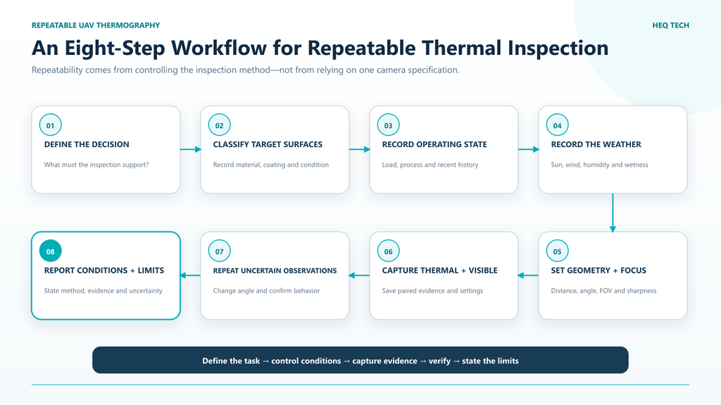
Repeatability comes from controlling the inspection method, not from relying on one camera specification.
- Define the decision. State whether the mission is detecting an anomaly, comparing assets or requires separately verified object-surface temperature measurement.
- Classify the surfaces. Identify coatings, bare metals, glass, insulation and other materials that require different interpretation.
- Record operating state. Capture load, production state, startup time and other variables that create the expected thermal pattern.
- Record environmental conditions. Include sun, recent cloud, wind, precipitation, humidity, ambient temperature and relevant prior weather.
- Set geometry and focus. Choose a safe stand-off, sufficient pixels on target and a view as close to normal as practical.
- Capture thermal and visible evidence. Keep asset identification, time, position and camera settings connected to the image.
- Repeat uncertain observations. Change angle deliberately, compare equivalent targets and use an approved reference or ground check where needed.
- Report limits. Separate observed thermal patterns, environmental settings, verified measured values, assumptions and recommended confirmation work.
Questions for a thermal-payload RFQ or acceptance test
- Does the payload provide thermal imaging only, an environmental-temperature setting, spot measurement, area measurement or full-frame radiometric data?
- Which environmental-temperature, emissivity, reflected-temperature, distance and humidity controls are available?
- Are those values user-entered scene parameters, measured outputs or both?
- Are those parameters applied in the payload, controller application or post-processing software?
- Which thermal modes retain verified object-temperature measurement, and which are display-only?
- What are the stated measurement accuracy, calibration conditions and minimum target-size requirements?
- What thermal file format is recorded, and can measurement parameters be changed during analysis?
- How are thermal, visible, gimbal-angle, UAV-position and timestamp data synchronized?
- How does the system indicate non-uniformity correction, saturation or an out-of-range measurement?
- Can the supplier provide original thermal files from representative targets, distances and environmental conditions?
- Which acceptance test will reproduce the intended viewing angles, surfaces, loads and weather limits?
Frequently asked questions
Are infrared and thermal imaging different?
In industrial UAV use, “thermal imaging” means imaging infrared radiation associated with the target and its environment. The more useful distinction is between a thermal image that shows relative radiance patterns, an environmental-temperature setting used to describe scene conditions, and verified radiometric measurement that estimates an object’s surface temperature using calibration, a measurement tool and scene parameters.
Can higher thermal resolution solve an emissivity problem?
No. More detector pixels can improve spatial sampling, but they do not make a reflective surface emit more of its own radiation. Resolution, emissivity compensation and measurement accuracy address different parts of the problem.
Can a thermal camera inspect polished metal from a drone?
It can show the radiation pattern reaching the detector, but polished metal often has low emissivity and strong reflections. Change the viewing angle, compare equivalent components and treat the result as qualitative unless the exact payload has separately verified object-temperature measurement capability and the inspection method controls emissivity, reflections and geometry.
Does an IP rating mean thermal inspection in rain is accurate?
No. An IP classification addresses enclosure protection under defined tests. Rain can still cool the target, change the surface, attenuate the path and contaminate the lens. Aircraft weather limits and local operating requirements must also be considered separately.
Is every thermal hot spot a fault?
No. A hot pattern may result from normal load, solar heating, reflection, insulation, airflow, material differences or an actual defect. Classification needs asset context, comparable references and, where required, confirmation by a qualified person.
Can a long-wave thermal camera see through ordinary glass?
Do not assume it can. Many ordinary windows are not transparent in the long-wave infrared band and can behave as reflective or opaque surfaces. If an inspection must look through a window, use an approved infrared window with known spectral transmission and apply the required compensation.
Technical references
- HEQ UAV Tech, K40T Quad-Sensor AI Gimbal Camera specifications.
- ISO, ISO 18434-1:2008, Condition monitoring and diagnostics of machines—Thermography—Part 1: General procedures.
- ISO, ISO 18434-2:2019, Condition monitoring and diagnostics of machine systems—Thermography—Part 2: Image interpretation and diagnostics.
- Teledyne FLIR, Thermographic measurement techniques.
- Teledyne FLIR, How emissivity affects thermal imaging.
- Teledyne FLIR, Thermal camera placement and viewing-angle guidance.