A thermal camera for drones is often compared by four headline specifications: resolution, pixel pitch, frame rate and field of view. These numbers are related, but they do not describe the same kind of performance. Reading one in isolation can lead to the wrong payload choice.
Resolution tells you how many detector samples form the thermal image. Pixel pitch describes the physical spacing of those detector elements. Frame rate tells you how often the image updates. Field of view, together with distance, determines how much of the scene fits into each frame. The lens connects these specifications by controlling the angular coverage and the approximate angle represented by each detector pixel.
This guide explains how the four specifications work together in an industrial drone inspection. It uses the HEQ K40T as a calculation example, while keeping the evaluation method applicable to other thermal payloads.
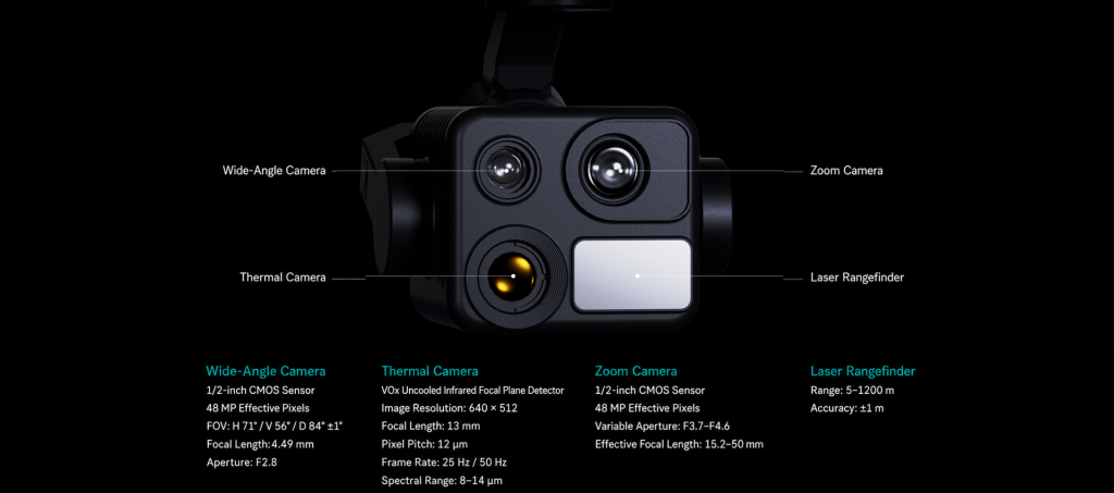
Specifications used to evaluate a thermal camera for drones.
The four specifications at a glance
| Specification | What it describes | Operational question it helps answer | What it does not prove |
|---|---|---|---|
| Thermal resolution | Number of detector samples across the image | How many native pixels are available to represent the scene? | That a small defect will be identifiable or a temperature reading will be accurate |
| Pixel pitch | Center-to-center spacing of detector elements | How does the detector geometry work with the lens? | Overall image quality by itself |
| Frame rate | Number of complete thermal frames produced per second | How frequently does the view update during motion? | More spatial detail or better temperature accuracy |
| Field of view | Angular width and height covered by the camera | How much area is visible from the planned distance? | Guaranteed detection, recognition or identification performance |
A fifth figure belongs in the discussion: lens focal length. For a given detector, a shorter focal length generally produces a wider field of view; a longer focal length produces a narrower view and places more pixels across the same target at the same distance. Sensor dimensions, lens design, focus and distortion also affect the result.
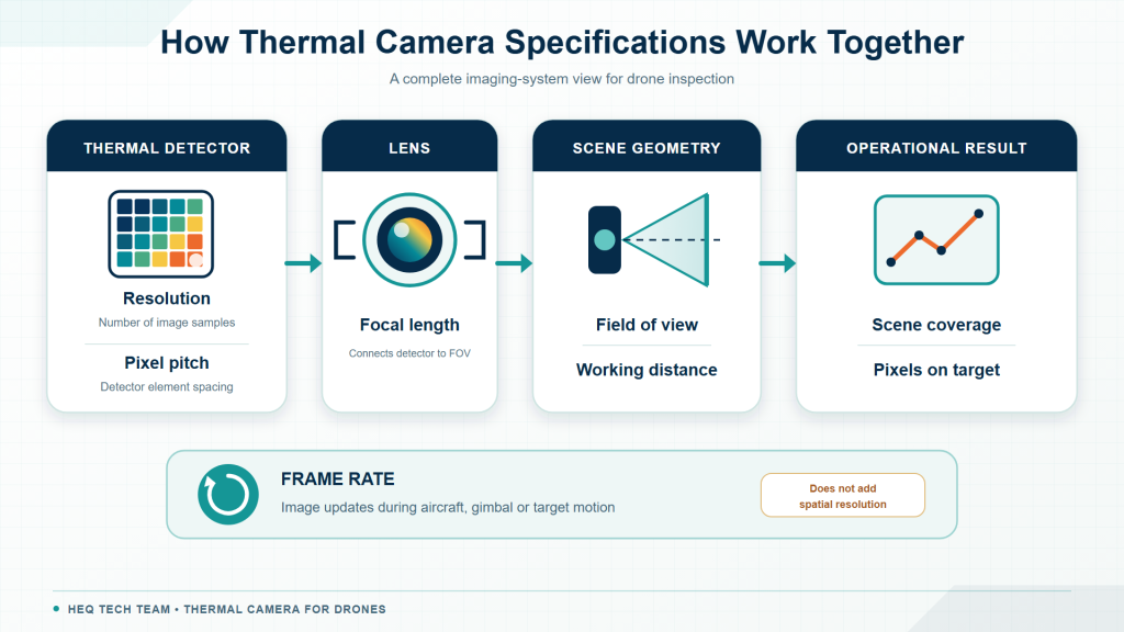
A useful thermal-camera evaluation connects detector, lens, distance and motion rather than ranking one number alone.
1. Thermal resolution: the number of native detector samples
A 640 x 512 thermal detector contains 327,680 detector elements. Each element contributes one sample to the native thermal image. That is much lower than the pixel count of a modern visible camera, but the two technologies capture different parts of the electromagnetic spectrum and should not be judged by a consumer-camera megapixel comparison.
More native thermal pixels can help in two ways. They can represent more scene detail at a similar field of view, or they can cover a wider area while preserving a useful number of pixels on a target. The practical result still depends on the lens, target size, distance, focus, stabilization, atmospheric transmission and the thermal contrast between the target and its background.
Resolution also needs a clear label. A manufacturer may describe native detector resolution, output video resolution, an upscaled image or an algorithmically enhanced image. These are not interchangeable. Upscaling can make a file larger and processing may improve visual interpretation, but neither changes the number of physical detector elements that captured the scene.
Digital zoom and cropping enlarge existing thermal samples. They do not create the same evidence as placing more native detector pixels on the target during capture.
When comparing thermal cameras for drones, request original files at the native output size. Examine the uncropped frame first, then the crop. A close-up shown without its original field of view can make it difficult to judge how many pixels actually represented the feature.
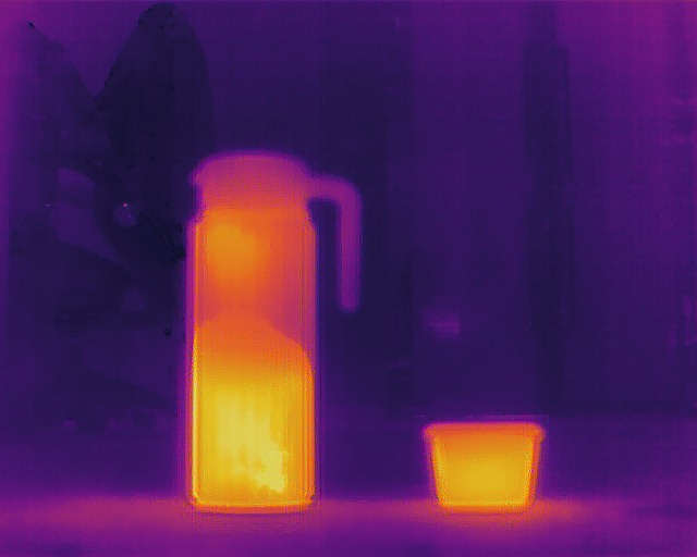
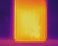
Show the native frame and crop together so reviewers can see the original pixel coverage.
2. Pixel pitch: detector geometry, not a quality score
Pixel pitch is the center-to-center spacing between adjacent detector elements. It is commonly stated in micrometers, such as 12 um or 17 um. If two detectors have the same pixel count, the smaller-pitch detector has a smaller physical active area. That can support a more compact optical system, but it does not mean that the smaller number automatically produces the better thermal image.
The detector material, sensitivity, noise performance, readout electronics, calibration, optics and image processing all contribute to usable image quality. A procurement comparison should therefore avoid a simple “12 um beats 17 um” rule. Compare complete camera systems under the same target, distance and environmental conditions.
Pixel pitch becomes especially useful when it is combined with focal length. A first-order approximation of the instantaneous field of view, or IFOV, for one pixel is:
IFOV in radians is approximately pixel pitch divided by focal length.
For a 12 um detector paired with a 13 mm lens, the approximate IFOV is 0.000923 radians, or 0.923 milliradians. At 100 m, one detector pixel therefore spans approximately 92 mm at the target plane. This is a geometric pixel footprint, not a promise that a 92 mm object can be detected, recognized, diagnosed or measured accurately. Real tasks generally need multiple pixels across the relevant feature, plus sufficient thermal contrast and image quality.
3. Field of view: coverage versus pixels on target
Field of view is the angular extent of the scene captured by the camera, normally stated as horizontal and vertical angles. A wide FOV covers more ground and makes target acquisition easier. A narrow FOV covers less ground but places more of the detector across a target of the same size and distance.
This creates an unavoidable coverage-detail tradeoff. A wide thermal view may be efficient for scanning a roof, solar array or industrial site. A narrower thermal view may be preferable when a small component must occupy more pixels while the aircraft remains at a stand-off distance. Neither lens is universally better.
For a first-order estimate, the scene width at a known working distance can be calculated as:
Scene width = 2 x distance x tan(horizontal FOV / 2)
The same calculation applies vertically using the vertical FOV. This relationship is explained in the Edmund Optics field-of-view guide. It is an approximation: lens distortion, focus, entrance-pupil position and the actual distance to the target surface can change the captured dimensions.
K40T field-of-view example
The current K40T specification table lists a 640 x 512 detector, 12 um pixel pitch, 13 mm focal length and 33.5 degrees x 26.9 degrees FOV. The table below applies the published FOV to several stand-off distances and applies the 12 um / 13 mm IFOV approximation to the pixel footprint.
| Distance to target | Approx. scene width | Approx. scene height | Approx. one-pixel footprint |
|---|---|---|---|
| 25 m | 15.0 m | 12.0 m | 23 mm |
| 50 m | 30.1 m | 23.9 m | 46 mm |
| 100 m | 60.2 m | 47.8 m | 92 mm |
| 200 m | 120.4 m | 95.7 m | 185 mm |
These values are planning estimates, not acceptance criteria. An inspection team should define the smallest relevant feature and the number of pixels it needs across that feature, then validate the result with representative flight samples. Detection of a thermal contrast, recognition of a component and diagnosis of its condition are different performance thresholds.
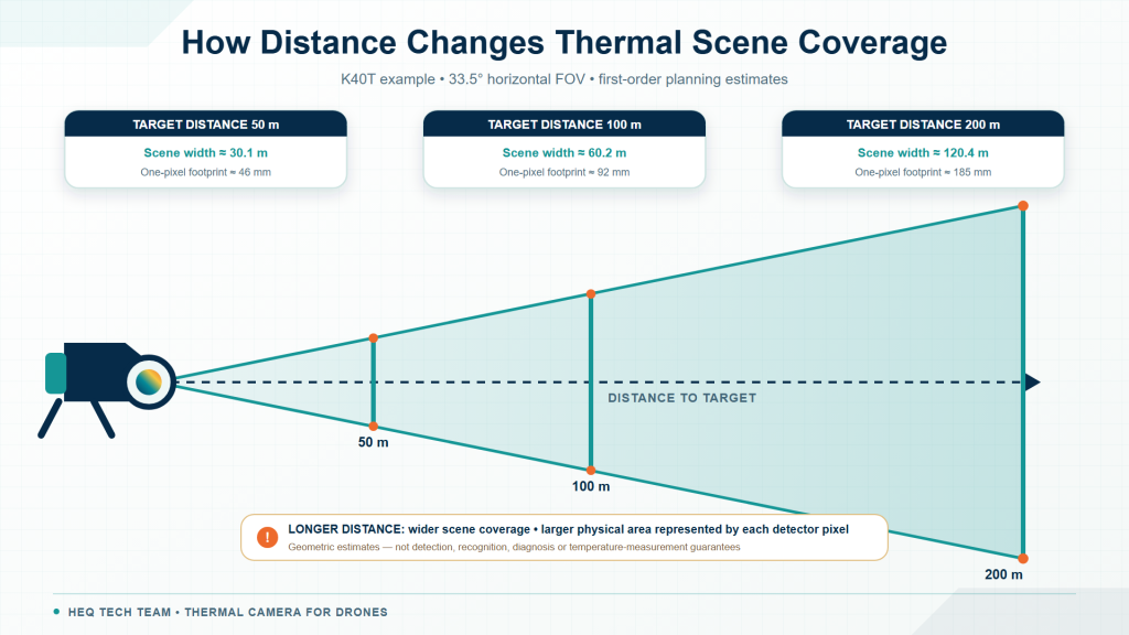
The camera angle stays constant, but scene coverage and the physical area represented by each pixel increase with distance.
4. Frame rate: why the current 25 Hz workflow matters
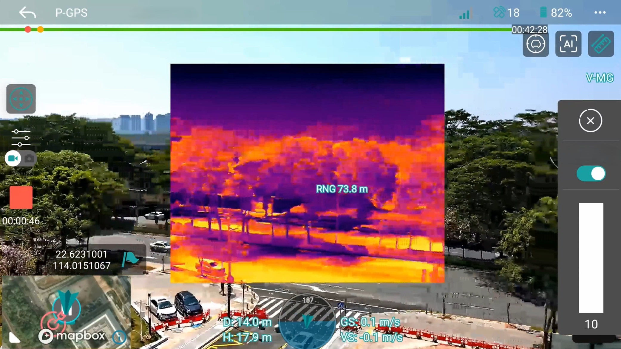
Frame rate is the number of complete thermal images produced each second. In the current HEQ K40T operating workflow, the thermal channel normally runs at 25 Hz, meaning that it updates 25 times per second. The HEQ Gimbal Studio app does not present the operator with a button for switching between 25 Hz and 50 Hz, so 50 Hz should not be described as a routine user-selectable mode.
The 25 Hz default provides continuous thermal imagery for normal industrial inspection movements and supports the thermometry function available in the current app. However, frame rate and thermometry are separate specifications. A 25 Hz update rate does not by itself establish temperature-measurement range, accuracy or calibration.
For roof, solar, electrical and other industrial inspections, the more useful question is whether the complete 25 Hz system remains clear and responsive at the planned aircraft speed and gimbal movement. Stabilization, focus, recording format, display latency, transmission bandwidth and compression can all affect what the operator sees, even when the detector frame rate remains unchanged.
The K40T product specification currently lists 25/50 Hz, but that listing should not be interpreted as an in-app frame-rate selector. If a buyer requires a configuration other than the standard 25 Hz workflow, the delivered hardware, firmware and software support should be confirmed with HEQ before procurement.
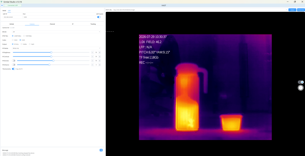
HEQ Gimbal Studio showing K40T thermal video and thermometry controls.
How the specifications work together in real inspections
Roof and solar-array coverage
For area surveys, the planned ground coverage and overlap often drive the choice. A wider FOV can cover more surface per frame, but increasing altitude also increases the physical area represented by each pixel. The team needs enough pixels across the smallest thermal pattern that matters to its inspection method. Flight speed and frame rate then affect how frequently the scene is sampled along the route.
Power and industrial components
When a connector, bearing, pipe feature or electrical component is small relative to the stand-off distance, pixels on target become the limiting factor. Native resolution, lens FOV, distance and stabilization must be evaluated together. A digital crop can help a reviewer look at the available samples, but it cannot replace suitable optical framing at capture.
Civilian security and patrol
For authorized industrial-site or perimeter patrol, a wider view supports search and orientation, while a faster frame rate can support smoother observation of motion. The required detail must still be defined in advance. Detecting a heat-emitting object is different from recognizing what it is, and thermal imagery should be paired with suitable visible context where lawful and appropriate.
What these four numbers do not tell you
Resolution, pixel pitch, frame rate and FOV describe important parts of the imaging chain. They do not fully define thermal performance. A serious payload comparison should also examine:
- Thermal sensitivity: Request NETD and the conditions under which it is specified. Lower noise can make small temperature differences easier to distinguish, but test methods and scene conditions matter.
- Focus: Determine whether the lens is fixed-focus or adjustable and confirm useful focus across the planned distance range.
- Radiometric capability: Confirm whether the camera stores calibrated temperature data or only produces a thermal image.
- Measurement range and accuracy: If temperature measurement is required, request the range, accuracy statement, test conditions, calibration process and supported file format.
- Emissivity and reflected temperature controls: Low-emissivity surfaces, especially polished metals, can reflect thermal radiation from their surroundings and complicate interpretation.
- Original data and processing: Ask what palettes, enhancement, compression, gain modes and non-uniformity corrections are applied, and whether original data can be exported.
- Stabilization and integration: Review gimbal performance, latency, recording, metadata, control interfaces and compatibility with the aircraft and ground station.
- Environmental performance: Confirm temperature limits, ingress protection and performance in the expected wind, humidity, haze and precipitation conditions.
FLIR’s emissivity guidance explains why polished, low-emissivity materials may reflect surrounding thermal radiation and why reflected temperature matters to measurement. This is one reason that a sharp-looking thermal image should not be treated as an automatic temperature diagnosis.
K40T thermal specifications: what can be concluded
The current K40T product page publishes the following thermal-channel specifications. They support an imaging-system evaluation, but only within the limits shown.
| Published K40T specification | What it supports | Important limit |
|---|---|---|
| VOx uncooled infrared focal-plane detector | Identifies the detector type | Does not state sensitivity or measurement accuracy |
| 640 x 512 native resolution | Defines the number of detector samples | Does not guarantee task-level detection or diagnosis |
| 12 um pixel pitch | Supports detector-and-lens geometry calculations | Is not a standalone image-quality ranking |
| 13 mm focal length | Helps connect detector size to FOV | Published FOV should be used for planning and then field-verified |
| 33.5 degrees x 26.9 degrees FOV | Supports first-order scene-coverage estimates | Does not define pixels required for a specific inspection task |
| 25/50 Hz listed; 25 Hz operational default | Describes the published detector-rate options and current HEQ workflow | Gimbal Studio does not provide an operator-facing 25/50 Hz selector; confirm any alternate configuration separately |
| 8-14 um spectral band | Identifies the long-wave infrared operating band | Does not state radiometric output capability |
| F1.2 aperture | Describes part of the optical system | Does not replace a sensitivity or end-to-end image test |
The current table does not publish NETD, temperature-measurement range, measurement accuracy or a radiometric file format. This article therefore treats the K40T thermal channel as a thermal imaging and anomaly-detection tool. If calibrated temperature measurement is part of the purchasing requirement, HEQ should confirm the applicable product capability and documentation before that claim is added to a specification or inspection procedure.
K40T also combines wide-angle and telephoto visible cameras with its thermal channel. That multi-sensor design supports a broader inspection workflow: use thermal contrast to direct attention, then use visible context to locate and review the physical feature. For more on that sequence, see how thermal and zoom sensors work together in a UAV inspection payload.
A procurement checklist for thermal drone payloads
- Define the task: State whether the mission requires detection, recognition, visible confirmation, qualitative thermal comparison or calibrated temperature measurement.
- Define the smallest relevant feature: Record its physical dimensions and expected thermal contrast.
- Set the working-distance range: Include site restrictions, obstacle clearance and expected aircraft position.
- Calculate scene coverage: Use the published FOV to estimate width and height at the planned distances.
- Estimate pixels on target: Use detector resolution and FOV, or pixel pitch and focal length, then apply a conservative task-specific threshold.
- Check motion requirements: Compare frame-rate options using representative aircraft and gimbal movement.
- Request original samples: Ask for uncropped thermal files at multiple known distances, plus visible context and documented conditions.
- Verify radiometry separately: If temperature data is required, obtain the range, accuracy, calibration and file-format documentation.
- Test the complete system: Evaluate focus, stabilization, transmission, recording, metadata and integration, not only the camera module.
- Write acceptance criteria: Base approval on a representative field task rather than a specification-sheet ranking.
The practical takeaway
A strong thermal camera for drones is not selected by choosing the largest number in one column. Resolution defines native sampling. Pixel pitch helps describe detector geometry. Focal length and FOV determine angular coverage. Distance turns that angle into scene dimensions and an approximate pixel footprint. Frame rate determines how frequently that view updates.
The correct combination depends on the target, required evidence, working distance, motion and environmental conditions. Begin with the inspection task, calculate the expected geometry, and then verify it with original files from a representative flight.
Frequently asked questions
Is 640 x 512 a good resolution for a drone thermal camera?
It provides 327,680 native thermal samples and can support many inspection workflows, but “good” depends on the task. The target must occupy enough pixels at the planned distance, with adequate thermal contrast, focus and stability. A field test is more meaningful than resolution alone.
Is a 12 um pixel pitch better than 17 um?
Not automatically. A smaller pitch changes the detector’s physical dimensions and its relationship with the lens. Sensitivity, optics, calibration, noise, processing and complete-system performance also matter. Compare matched samples rather than ranking pitch alone.
Is 25 Hz sufficient for industrial drone inspection?
For the current K40T workflow, 25 Hz is the normal operating default and is suitable for many stabilized roof, solar, electrical and industrial inspection movements. The requirement should still be validated at the planned aircraft speed, gimbal motion and working distance. Frame rate does not determine native resolution or thermometry accuracy.
How does FOV affect drone inspection distance?
At a fixed angle, scene coverage grows as distance increases. Each detector pixel then represents a larger physical area at the target, so small features occupy fewer pixels. A narrower FOV places more pixels on the target at the same distance but covers less of the scene.
Can digital zoom improve native thermal resolution?
No. Digital zoom enlarges or processes the samples already captured. It may make viewing easier, but it does not add physical detector elements or replace suitable lens choice and working distance.
Does a 640 x 512 thermal camera measure temperature accurately?
Resolution does not establish temperature-measurement capability. Accurate radiometric work requires a camera designed and calibrated for measurement, documented range and accuracy, appropriate emissivity and reflected-temperature settings, suitable environmental conditions and a validated inspection method.